External BIOS Update (AN07): Difference between revisions
Eugenbeluga (talk | contribs) No edit summary Tag: Manual revert |
Eugenbeluga (talk | contribs) No edit summary |
||
| Line 65: | Line 65: | ||
*SPI flash device with the current BIOS pre-programmed | *SPI flash device with the current BIOS pre-programmed | ||
For '''supported SPI flash devices''', refer to [[ | For '''supported SPI flash devices''', refer to [[Supported SPI Flash Devices for BIOS]]. | ||
For instruction how to pre-program an external BIOS flash device, refer to [[External_BIOS_Update_(AN07)#Pre-programming the SPI Flash Device|Pre-Programming the SPI Flash Device]]. | For instruction how to pre-program an external BIOS flash device, refer to [[External_BIOS_Update_(AN07)#Pre-programming the SPI Flash Device|Pre-Programming the SPI Flash Device]]. | ||
Latest revision as of 10:11, 4 December 2025
| Affected Products | x86-based products |
|---|
Preface
This application note describes how to proceed if the congatec Embedded BIOS needs to be updated from an SPI flash device when the image on the internal flash is corrupt and no longer functioning.
Terminology
| Term | Description |
|---|---|
| UEFI | Unified Extensible Firmware Interface |
| AMI | American Megatrends, Inc - congatec’s BIOS partner |
| Aptio | AMIs UEFI Firmware product |
| COM | Computer on Module |
| SBC | Single Board Computer |
Introduction
congatec embedded computer modules and single board computers use congatec embedded BIOS stored in an onboard SPI flash device. It is based on AMIs Aptio UEFI firmware solution.
This application note describes how to update a congatec BIOS from the external SPI flash located on the evaluation carrier board for the respective module or on the debug adapter for SBCs.
Updating from an external flash device may be necessary if the BIOS on the onboard flash is corrupt and no longer bootable.
The conga-TS170 and the BIOS binary file BQSLR011.bin is used as an example.
Required Equipment
The following equipment is required to perform a BIOS update from an external flash device.
Equipment for Modules Only
- congatec evaluation carrier board
- conga-TEVAL or TEVAL/COMe 3.0 for COM Express type 6 modules
- conga-X7/EVAL for COM Express type 7 modules
- conga-MEVAL for COM Express type 10 modules
- conga-QEVAL/Qseven 2.0 for Qseven modules
- conga-SEVAL for SMARC modules
- conga-HPC/EVAL-Server for COM-HPC Server modules
- conga-HPC/EVAL-Client for COM-HPC Client modules
- congatec CPU module
Equipment for Single Board Computers Only
- conga-MITX/debug card (PN047858)
- congatec MINI-ITX SBC
Additional Equipment
- Power Supply
- USB Keyboard
- Display
- SPI flash device with the current BIOS pre-programmed
For supported SPI flash devices, refer to Supported SPI Flash Devices for BIOS.
For instruction how to pre-program an external BIOS flash device, refer to Pre-Programming the SPI Flash Device.
Note:
The external BIOS flash chip must be the same size as the BIOS .bin file. An external flash chip larger than the BIOS file size might not work.
Software and Files
- Bootable DOS or UEFI shell USB memory stick
(refer to section Creating a Bootable USB Stick)
- BIOS binary file (contact the congatec technical support or visit the restricted area on the www.congatec.com to get the latest BIOS revision for the CPU product you are using)
- congatec System Utility, available for download at www.congatec.com
- cgutlcmd.exe (DOS command line version)
- cgutlcmd.efi (UEFI shell command line version)
Creating a Bootable USB Stick
Creating a Bootable FreeDOS USB Stick
- Download Rufus from https://rufus.ie/en/
- Insert the USB stick
- Launch and set up Rufus as shown in the screenshot below:
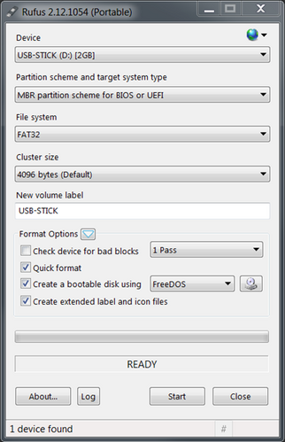
- Click Start
- Download the latest version of the congatec system utility (cgutil.zip) from www.congatec.com
- Copy the DOS command line version of the congatec system utility (cgutlcmd.exe) from cgutil.zip to the root directory of this FreeDOS USB stick
- Copy the desired BIOS binary file (*.bin file) for your product to the root directory of this FreeDOS USB stick
.png)
Creating a Bootable UEFI Shell USB Stick
Refer to AN31_Creating_an_UEFI_Stick on how to create a bootable UEFI shell stick.
After the UEFI shell stick is ready:
- Download the latest version of the congatec system utility (cgutil.zip) from www.congatec.com
- Copy the expanded UEFI shell command line version of the congatec system utility (cgutlcmd.efi) from cgutil.zip to the \efi directory of this UEFI shell USB stick.
- Copy the desired BIOS binary file (*.bin file) for your product to the \efi directory of this UEFI shell USB stick.
Pre-programming the SPI Flash Device
There are two ways for preprogramming the external SPI flash device.
Programming with a Flash Programmer
This is a general overview of the key points you need to be aware of when programming the SPI flash with a flash programmer.
The flash devices have a SOIC8 or SOIC16 footprint and need the corresponding adapter.
Caution:
There are different voltages for different products. Applying 3.3V to a 1.8V SPI flash will destroy the chip. The SPI interface on the conga-SEVAL runs at 1.8V, while other evaluation carriers and the MITX debug card run at 3.3V.
Refer to section Additional Equipment for the required SPI flash device and the correct BIOS binary file.
After making sure you got the right programmer and adapter for the SPI flash device, program the BIOS binary onto the SPI flash.
Note:
Check the flash size of your product in the respective user’s guide. For products with a ≥32MByte flash device, set the flash programmer to 4-Byte address mode.
If you do not have a flash programmer, use the update procedure described in the following section.
Programming of External BIOS Flash with CGUTIL
In this step, a functioning product of the same type and with the same BIOS flash size is used together with the evaluation carrier/MITX debug card to preprogram the external SPI flash device. The procedure is similar to the actual flash update you will see in the section Onboard BIOS Flash Update Procedure. We recommend a product with the same part number to program the external flash. This way, it is not possible to accidentally program the wrong BIOS onto the working board.
- Connect the necessary peripherals and power supply to the system (evaluation carrier + working module or working Mini-ITX board + debug card).
- Insert the empty SPI flash into the socket and set the DIP switches to boot from on-module BIOS. Please refer to section External BIOS Flash Location for the exact position.
- Plug in the USB boot medium with FreeDos or UEFI shell containing the BIOS flash tool cgutlcmd and the BIOS binary file. Both files should be in the same directory.
- Start the system and boot into the operating system on the USB stick.
- Navigate to the folder where cgutlcmd and the BIOS binary are located.
Note:
When using the UEFI shell to navigate to the files, you need to select the right file system first. To do this, enter "FSx:", when x stands for the number of the file system, the shell gave to the USB stick.
- Unlock the flash part by entering the following command:
cgutlcmd bflash /eu- If the flash part needs to be unlocked, the system will perform a power cycle in order to unlock it. This is necessary to do a full update in the next step. A full update means that not only the UEFI firmware content will be flashed to the flash part but also any additional firmware that is required (for example ME and TXE binaries).
Note:
Check the flash size of your product in the respective user’s guide. For products with a ≥32MByte flash device, follow these additional steps:
a) During the power cycle of step 6, switch the ATX power supply off (G3) while the main power is off (S5)
b) Set the DIP switches to boot from external BIOS
c) Turn the ATX power supply on (G3 --> S5)
d) Set the DIP switches back to boot from on-module BIOS
e) Press the power button for five seconds, release the button and then briefly press it again. The system should turn on
f) Wait until the system finished booting.
- Navigate to the folder where cgutlcmd and the BIOS binary file are located and enter the following command:
cgutlcmd bflash BIOSNAME.bin /efm /d- The parameter
BIOSNAMEstands for the name of the BIOS file, e.g. “BQSLR011.bin”
Note:
The parameter “/efm” will force a full flash update (UEFI firmware + extended area) without doing an automatic reboot after the flash update is finished. Usually, it is sufficient to only use “/em” because the congatec system utility auto detects if a full update is necessary and skips it when not, thereby saving much time. However, it is safer to force the full update when an external update is done.
The parameter “/d” allows you to switch to another flash part, in order to program the external SPI flash device.
When using a product with a different BIOS than the defective one for the external update, the “/f” parameter is needed to program the BIOS. The “/f” parameters bypasses the built-in protection mechanism that only allows the user to program BIOS binary with the same 4 letter BIOS project name.
Please refer to BIOS Update (AN01) for more information about the different parameters used.
- After the prompt tells you that you may switch to another flash part, set the DIP switches to boot from external BIOS.
- Confirm by pressing any key, the update process will now start. Once completed, the message "BIOS successfully updated" will be displayed.
- Turn of the system. Your external SPI flash has been successfully prepared.
Note:
On some products, including the conga-xA5 (intel® Apollo Lake) product line, the SoC writes back information to the SPI flash during the first boot. This write-back will prevent other boards from booting with the same flash. Therefore, it is important to use the /efm parameter when programming the external SPI flash, to ensure the board does not reboot automatically after the update.
Onboard BIOS Flash Update Procedure
In this section, the pre-programmed SPI flash device is used to boot up the product and program the on-module BIOS flash.
- Insert the pre-programmed SPI flash into the socket and set the DIP switch to boot from external BIOS. Refer to the section External BIOS Flash Location for the exact position.
- Connect the necessary peripherals and power supply to the system (eval carrier + non-booting module or Mini-ITX board + debug card).
- Plug in the USB boot medium with FreeDOS or UEFI shell containing the BIOS flash tool cgutlcmd and the BIOS binary file. Both files should be in the same directory.
- Start the system and boot into the operating system on the USB stick.
- Navigate to the folder where cgutlcmd and the BIOS binary are located.
Note:
When using the UEFI shell in order to navigate to the files, you need to select the right file system first. To do this type "Fsx:", where x stands for the number of the file system the UEFI shell gave to the USB stick.
- Unlock the flash part by entering following command:
cgutlcmd bflash /eu- If the flash part needs to be unlocked, the system will perform a power cycle in order to unlock it. This is necessary to do a full update in the next step. A full update means that not only the UEFI firmware content will be flashed to the flash part but also any additional firmware that is required (for example ME and TXE binaries).
- Navigate to the folder where cgutlcmd and the BIOS binary are located and enter the following command:
cgutlcmd bflash BIOSNAME.bin /ef /d- The parameter
BIOSNAMEstands for the name of the BIOS file, e.g. "BQSLR011.bin":
Note:
The parameter “/ef” will force a full flash update (UEFI firmware + extended area). Usually, it is sufficient to only use “/e” because the congatec system utility auto detects if a full update is necessary and skips it when not, thereby saving much time. However, it is safer to force the full update when an external update is done.
When the BIOS does not have an extended area, the tool will ignore this parameter.
The parameter “/d” allows you to switch to another flash part to program the external SPI flash device.
Please refer to BIOS Update (AN01) for more information about the different parameters used.
- After the prompt tells you that you may switch to another flash part, switch to the onboard BIOS with the DIP switch.
- Confirm by pressing any key to start the update process. Once completed, the message “BIOS successfully updated” will be displayed.
- The system restarts. Your BIOS has been successfully updated and the product should be able to boot again.
Note:
On some products, including the conga-xA5 (intel® Apollo Lake) product line, the SoC writes back information to the SPI flash during the first boot. This write-back will prevent other boards from booting with the same flash. Therefore, we recommend to prepare a new SPI flash for every board that needs to be recovered.
External BIOS Flash Location
conga-TEVAL
.png)
conga-TEVAL/COMe 3.0
.png)
conga-X7EVAL
.png)
conga-MEVAL
.png)
conga-QEVAL/Qseven 2.0
.png)
When the DIP switch is set to external the LED D4 is lit.
conga-SEVAL
.png)
When the DIP switch is set to external, the LED D4 is lit.
Note:
Given the limited availability of 1.8V-flash devices with ≥32Mbyte in SOIC8-packages, you might consider using a 1.8V WSON8-package. An appropriate adapter can be used for compatibility with the conga-SEVAL. For guidance on programming the flash device, refer to sections 4.1 and 4.2.
Mini ITX
.png)
conga-HPC/EVAL-Server
.png)
conga-HPC/EVAL-Client
.png)