U.2 Introduction (AN44): Difference between revisions
Eugenbeluga (talk | contribs) No edit summary |
Eugenbeluga (talk | contribs) No edit summary |
||
| Line 659: | Line 659: | ||
[[Category:Application Notes]] | [[Category:Application Notes]] | ||
Revision as of 03:49, 22 November 2024
| Affected Products | All products |
|---|
Preface
This Application Note introduces the SFF-8639 (U.2) interface. The goal is to give an overview of the technology and hint on how to design-in this technology for customer carrier boards.
Terminology
| Term | Description |
|---|---|
| NVMe | Non-Volatile Memory Express |
| SSD | Solid State Drive |
| SAS | Serial-Attached SCSI |
| SATA | Serial ATA |
| SFF | Small Form Factor |
| OD | Open-Drain |
U.2 / SFF-8639 Introduction
Introduction
The U.2 specification (initially SFF-8639), which is released by the PCI-SIG group, describes a hardware interface that supports several SSD interface technologies.
This specification is used mostly for connecting high performance NVMe SSDs. For overview of the NVMe protocol, visit www.congatec.com and view the Tech Note NVMe support on congatec COMs and SBCs in the restricted area of the website.
To enable NVMe SSDs, the U.2 pinout features up to four PCIe lanes for inter-connection. Most often, this specification is used for SSDs in 2.5” form factor. This makes implementing the U.2 form factor a good method of scaling up the system speed while still being able to keep the same physical form factor for existing SATA-based SSDs.
In addition to PCIe-based SSDs, the interface also supports SAS and SATA. This enables the connector to work with different SSD technologies.
This Application Note is concerned with U.2 specification pinout as well as topologies that can be used to design-in the interface.
Backward Compatibility
One of the advantages of this specification is that it allows SATA, SAS and U.2 NVMe SSDs to be used on the same U.2 connector. This means that systems can be equipped with different types of SSD, depending on the demands of the system. In that way, the system can be scaled to perform different tasks, thereby improving the overall price efficiency of the design.
Advantages
U.2 SSDs are often used in data centers and server-related ecosystems. The SSD housing of a U.2 SSD is bigger and more ruggedized when compared to the bare PCB M.2 SSDs. This also allows U.2 devices to feature a bigger overall capacity.
U.2 devices can support hot-plug and hot-swap features. This capability allows new devices to be connected to the platform (hot-plug) or devices of the same type can be swapped out (hot-swap) while the system is up and running. The following conditions need to be met to support these features:
- The target SSD needs to support unplanned power loss.
- The BIOS of the congatec module you want to use needs PCIe hot-plug support.
U.2 SSDs often feature advanced power loss protection. This means that in a surprise power loss event, mandatory data transactions that have been cached can still be completed, making the SSD more robust to corruption in unstable power environments.
Note:
If you are unsure about hot-plug support on your congatec module, contact your FAE.
Connector Overview
This chapter gives a general overview of the U.2 connector. Sub-section U.2 Connector Overview highlights the overall U.2 connector while sub-section General U.2 Connector Pinout lists the pinout of all supported interfaces.
U.2 Connector Overview
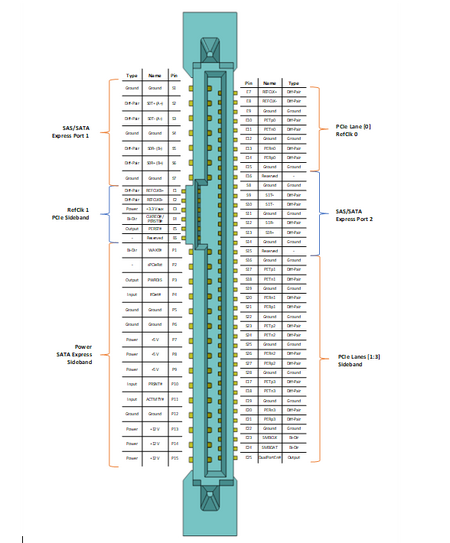
Figure 1: U.2 Connector Overview

General U.2 Connector Pinout
The table below lists the pinout of interfaces that are supported with U.2
Please note that for SATA and SATA Express implementations on U.2, the below signal names do not match the SATA specification exactly.
| Pin | Name | Type | PCIe NVMe | SATA | SATA Express | SAS x4 |
|---|---|---|---|---|---|---|
| P1 | WAKE# | Bi-Dir | Optional | |||
| P2 | sPCIeRst | - | ||||
| P3 | PWRDIS | Output | Optional | |||
| P4 | IfDet# | Input | Optional | Optional | Optional | |
| P5 | Ground | Ground | ||||
| P6 | Ground | Ground | ||||
| P7 | +5 V | Power | ||||
| P8 | +5 V | Power | ||||
| P9 | +5 V | Power | ||||
| P10 | PRSNT# | Input | Optional | Optional | ||
| P11 | ACTIVITY# | Input | Optional | Optional | ||
| P12 | Ground | Ground | Optional | Optional | ||
| P13 | +12 V | Power | ||||
| P14 | +12 V | Power | ||||
| P15 | +12 V | Power | ||||
| S1 | Ground | Ground | ||||
| S2 | S0T+ (A+) | Diff-Pair | ||||
| S3 | S0T- (A-) | Diff-Pair | ||||
| S4 | Ground | Ground | ||||
| S5 | S0R- (B-) | Diff-Pair | ||||
| S6 | S0R+ (B+) | Diff-Pair | ||||
| S7 | Ground | Ground | ||||
| S8 | Ground | Ground | ||||
| S9 | S1T+ | Diff-Pair | ||||
| S10 | S1T- | Diff-Pair | ||||
| S11 | Ground | Ground | ||||
| S12 | S1R- | Diff-Pair | ||||
| S13 | S1R+ | Diff-Pair | ||||
| S14 | Ground | Ground | ||||
| S15 | Reserved | - | ||||
| S16 | Ground | Ground | ||||
| S17 | PETp1 | Diff-Pair | ||||
| S18 | PETn1 | Diff-Pair | ||||
| S19 | Ground | Ground | ||||
| S20 | PERn1 | Diff-Pair | ||||
| S21 | PERp1 | Diff-Pair | ||||
| S22 | Ground | Ground | ||||
| S23 | PETp2 | Diff-Pair | ||||
| S24 | PETn2 | Diff-Pair | ||||
| S25 | Ground | Ground | ||||
| S26 | PERn2 | Diff-Pair | ||||
| S27 | PERp2 | Diff-Pair | ||||
| S28 | Ground | Ground | ||||
| E1 | REFCLKB+ | Diff-Pair | DualPort Only | |||
| E2 | REFCLKB- | Diff-Pair | DualPort Only | |||
| E3 | +3.3 Vaux | Power | Optional | |||
| E4 | CLKREQ#/
PERSTB# |
CLKREQ# is SSD
OD-Output |
||||
| E5 | PERST# | Output | ||||
| E6 | Reserved | - | ||||
| E7 | REFCLK+ | Diff-Pair | Optional | |||
| E8 | REFCLK- | Diff-Pair | Optional | |||
| E9 | Ground | Ground | Optional | |||
| E10 | PETp0 | Diff-Pair | ||||
| E11 | PETn0 | Diff-Pair | ||||
| E12 | Ground | Ground | ||||
| E13 | PERn0 | Diff-Pair | ||||
| E14 | PERp0 | Diff-Pair | ||||
| E15 | Ground | Ground | ||||
| E16 | Reserved | - | ||||
| E17 | PETp3 | Diff-Pair | ||||
| E18 | PETn3 | Diff-Pair | ||||
| E19 | Ground | Ground | ||||
| E20 | PERn3 | Diff-Pair | ||||
| E21 | PERp3 | Diff-Pair | ||||
| E22 | Ground | Ground | ||||
| E23 | SMBCLK | Bi-Dir | Optional | |||
| E24 | SMBDAT | Bi-Dir | Optional | |||
| E25 | DualPortEn# | Output | DualPort Only |
Topologies
Direct Connect Topologies
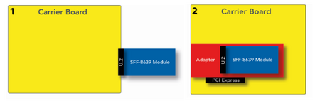
Figure 2: Topology 1 (left) and Topology 2 (right)
.png)
Topology 1 (left) connects U.2 module directly to the standard connector. In this topology, SATA, SAS and U.2 NVMe modules can be connected if the carrier board connector supports all U.2 interfaces.
Topology 2 (right) uses a PCI Express to U.2 adapter to connect a U.2 NVMe module. This topology can be useful for testing SFF-8639 modules on existing carrier boards that have PCIe slots. The adapters currently on the market feature a PCIe x4 lane configuration to utilize the full capacity of the device.
Topologies with Cabling
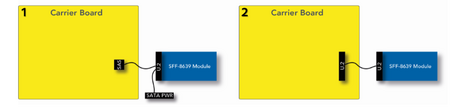
Figure 3: Topology 1 (left) and Topology 2 (right)
.png)
Cabling sets on the market right now focus on reusing existing SFF-8643 cables and connectors. These Mini-SAS HD cables are capable of carrying PCIe signals necessary for operating U.2 NVMe modules. Topology 1 depicts this setup. The carrier board features the SFF-8643 connector. An SFF-8643 to U.2 cable is used to connect the device. In addition, power is supplied to the U.2 module via a SATA power connector.
The second topology depicts a direct connection via U.2 cable.
Note:
Direct-connect U.2 cables are currently in development.
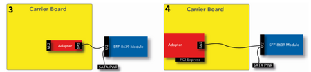
Figure 4: Topology 3 (left) and Topology 4 (right)
.png)
Topologies 3 and 4 use the HD Mini-SAS to U.2 cable as described in the first topology. Both setups can be used to determine the function of your U.2 module in existing carriers by using adapters on existing interfaces.
Adapters exist for M.2 as well as PCI Express interfaces.
Note:
Cabling and adapter solutions can negatively impact signal quality.