SPI TPM Reference Design (AN46)
Revision as of 11:26, 26 September 2024 by Piotrkorsak (talk | contribs)
| Affected Products | All SMARC products |
|---|
Preface
This application note provides the reference design and design notes for SPI TPM used on SMARC carrier boards.
Terminology
| Term | Description |
|---|---|
| TPM | Trusted Platform Module |
| TCG | Trusted Computing Group |
| LPC | Low Pin Count |
| SPI | Serial Peripheral Interface |
SPI TPM Reference Design
The Trusted Platform Module (TPM) is an international standard for security applications maintained by the Trusted Computing Group (TCG). The TCG considers the Intel Low Pin Count (LPC), Serial Peripheral Interface (SPI) and I2C interface for host communication. However, the SMARC 2.1 specification does not feature an Intel LPC interface and only non-x86 based platforms use the PC interface for the TPM. The reference design below shows how to design an SPI TPM to a SMARC 2.1 carrier board. The SPI TPM used in this reference design is an Infineon TPM SLB 9670VQ2.0. The TPM is connected to the SMARC SPIO interface.
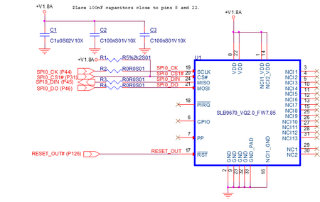
Figure 1: SPI TPM Reference Design
.png)
Design notes
- Typically, the on-module BIOS flash and the optional carrier baord BIOS flash device are connected to SMARC SPIO.
- SPIO_CS1# (SMARC pin P31) must be used for the active low SPI chip select input of the TPM.
- A pull-up resistor R1 is required to ensure the correct voltage level during start-up phase. Congatec' SMARC modules features the required series resistors for SPI on the module. However, we recommend to place resistors R2, R3 and R4 on the carrier board for signal tuning purpose. Additionally, we recommend minimizing the routing length on the SMARC carrier board to less than 2500mil.
- congatec SMARC modules do not support SPI TPM in the default configuration. Therefore, a custom BIOS version (e.g. SA50R916.bin for conga-Sa5) must be used in order to enable SPI TPM support and to configure the required SPI clock frequency. Additionally, it is required to disable the Intel Firmware-based TPM (fTPM) in BIOS setup menu.