Remote Control (AN02)
| Affected Products | Numerous |
|---|
Preface
This application note describes how the Remote Access is supported by the congatec Embedded BIOS (based on AMI Aptio V UEFI firmware) and can be used to control and configure headless systems without display or/and keyboard connected
Terminology
| Term | Description |
|---|---|
| BIOS | Basic Input Output System. BIOS is actually firmware, the software that is programmed into a ROM (Read-Only Memory) chip built onto the motherboard of a computer |
| UEFI | Unified Extensible Firmware Interface |
| POST | Power-on Self-Test. A diagnostic testing sequence run by a computer’s BIOS as the computer’s power is initially turned on |
| AMI | American Megatrends, Inc - congatec’s BIOS partner |
| Aptio V | AMIs next generation UEFI BIOS |
| SBC | Single Board Computer |
Introduction
Remote Access is accomplished through Serial Redirection, which allows video and keyboard redirection via a standard RS-232 serial port. The remote computer running communication software (HyperTerminal, Tera Term, minicom, etc.) must be connected with a null-modem cable. Video redirection via serial port is commonly used on “headless” systems, which run without the need for a VGA video display adapter.
Remote Access Requirements:
- Host system with a serial port, running a terminal program that supports XMODEM transfer protocol (HyperTerminal or Tera Term for Microsoft Windows, minicom for Linux/FreeBSD, etc.)
- Target system with a serial port either on the Single Board Computer (SBC) or on the carrier board when using a module. The Serial Port Console Redirection can always be enabled if an UART port (routed to Super I/O) is implemented on the carrier board. Check the user's guide of your module whether or not the onboard UARTs support Serial Port Console Redirection.
- Null-modem cable
Attach the null-modem cable to the serial port of the congatec SBC or module (“target”). Attach the other end of the null-modem cable to a system running the terminal program (“host”).
Remote Access Configuration
Remote Access functionality on the target system can be enabled in the BIOS Setup:
- Press <Del> key during startup to enter BIOS setup.
- Select 'Advanced' menu.
- Enter 'Serial Port Console Redirection'.
- Enable Remote Access/Console Redirection. After the Remote Access/Console Redirection has been enabled a series of configuration parameters will appear The above settings specify how the host and the target system will exchange data. Both systems must have the same or compatible settings.
- After the Remote Access/Console Redirection has been enabled a series of configuration parameters will appear
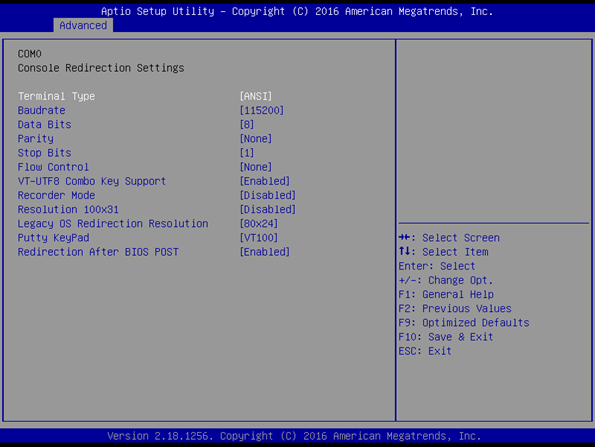
The above settings specify how the host and the target system will exchange data. Both systems must have the same or compatible settings.
.png)
Terminal Type (Type of Emulation):
- ANSI : Extended ASCII char set.
- VT100 : ASCII char set.
- VT100+ : Extends VT100 to support color, Function keys, etc.
- VT-UTF8 : Uses UTF8 encoding to map Unicode chars to 1 or more bytes.
Bits Per Second:
Selects serial port transmission speed. The speed must be matched on the other side. Long or noisy lines may require lower speeds. The options are 9600, 19200, 38400, 57600 and 115200 bps.
Data Bits:
Number of message data bits. The options are 7 and 8 data bits.
Parity:
A parity bit can be sent with the data bits to detect transmission errors.
The parity options are:
- Even: parity bit is 0 if the number of 1's in the data bits is even.
- Odd: parity bit is 0 if number of 1's in the data bits is odd.
- Mark: parity bit is always 1.
- Space: Parity bit is always 0.
Mark and space parity do not allow for error detection. They can be used as an additional data bit.
Stop Bits:
Stop bits indicate the end of a serial data packet. The standard setting is 1 stop bit. Communication with slow devices may require more than 1 stop bit. The options are 1 and 2 stop bits.
Flow Control:
Flow control can prevent data loss from buffer overflow. When sending data, if the receiving buffers are full, a 'stop' signal can be sent to stop the data flow. Once the buffers are empty, a 'start' signal can be sent to re-start the flow. Software flow control uses start/stop ASCII chars, which slows down the data flow and can be problematic if binary data is being sent.
The flow control options are:
- None
- Hardware CTS/RTS: HW flow uses two wires to send start/stop signals.
VT-UTF8 Combo Key Support:
Enables the VT-UTF8 combination key support for ANSI/VT100 terminals.
Recorder mode:
In this mode only text is sent to capture the terminal data. Use the recorder mode to capture post message data for analyzing. It is helpful in getting information, like recording post messages on reboots.
Resolution 100×31:
Applications like Putty can support any resolution, other than normal 80×24 resolution, supported by hyper terminal. Since we support 100×31, this option is included to use in such application.
- Enable - Enables extended resolution
- Disable - Disables extended resolution
Legacy OS Redirection:
HyperTerminal supports only 80*24 lines. The problem with 80*24 mode is the first line is not displayed on hyperterminal. But applications like Putty can support 80*25 mode where all lines can be redirected. Both modes are supported, 80×24 and 80×25.
Putty KeyPad:
Allows to select the FunctionKey and KeyPad on Putty. The options are VT100, LINUX, XTERMR6, SCO, ESCN and VT400.
Redirection After BIOS POST:
Disabled: Turns off the redirection after POST / before booting to Legacy OS. Enable: which means redirection is enabled for Legacy OS.
Note:
Serial Redirection will not work with applications running in graphic mode and with Operating Systems running in protected mode.
Caution:
The configuration of the communication software used on the host system must correspond to the configuration used for the target's BIOS settings.
Remote Access Uses
Change BIOS Settings
Remote Access can be used to modify the BIOS settings (the Remote Access has to be enabled in the BIOS Setup). The BIOS Setup can be accessed by pressing the <Del> key on the host system’s keyboard. Then, the necessary BIOS settings can be made by following the instructions displayed on the right side of the BIOS Setup screen.
Choose Boot Device
By pressing the <F10> key on the host system’s keyboard, the boot menu can be accessed to choose the device from which the module should boot the operating system.
Perform DOS Commands
When DOS is used as operating system, Remote Access can be used to control the system and perform the needed DOS commands. In this case, the setting for 'Redirection after BIOS POST' must be set to 'Enable'.
Perform UEFI Shell Commands
When UEFI shell is booted, Remote Access can be used to control the system and perform the needed UEFI shell commands. In this case the settings for 'Redirection after BIOS POST' must be set to 'Enable'.